Available here.

The Atmel (now microchip) AVR family is a well-known 8-bit processor family and is used by many people. These chips were readily available in DIP packages, and could be programmed using a cheap AVR-ICSP programmer. Microchip has introduced new families of controllers with improved capabilities and lower prices. These are known as tinyAvr-1 (2016), and tinyAVR-2 (2020). We concentrate here on the AtTiny3226. It seems that all parts within a family group are identical in capabilities but differ only in pin count and memory size.
These new chips have many advantages:
There are many ways to start working with such a new controller. This document proposes a method using minimal requirements:
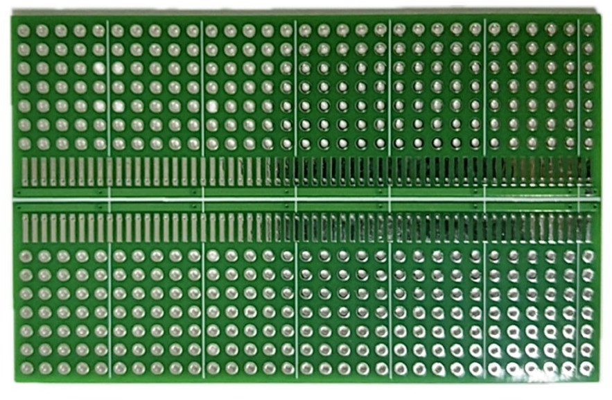
The chips come in a small SOIC-20 package. So mounting it on an 0.1" protoboard is not directly possible.
Here we use option 2: a special prototype board that supports THT- as well as SOIC components.
Available here.
And that's it. No crystal required. So you can use 17 of the 20 pins for your application.
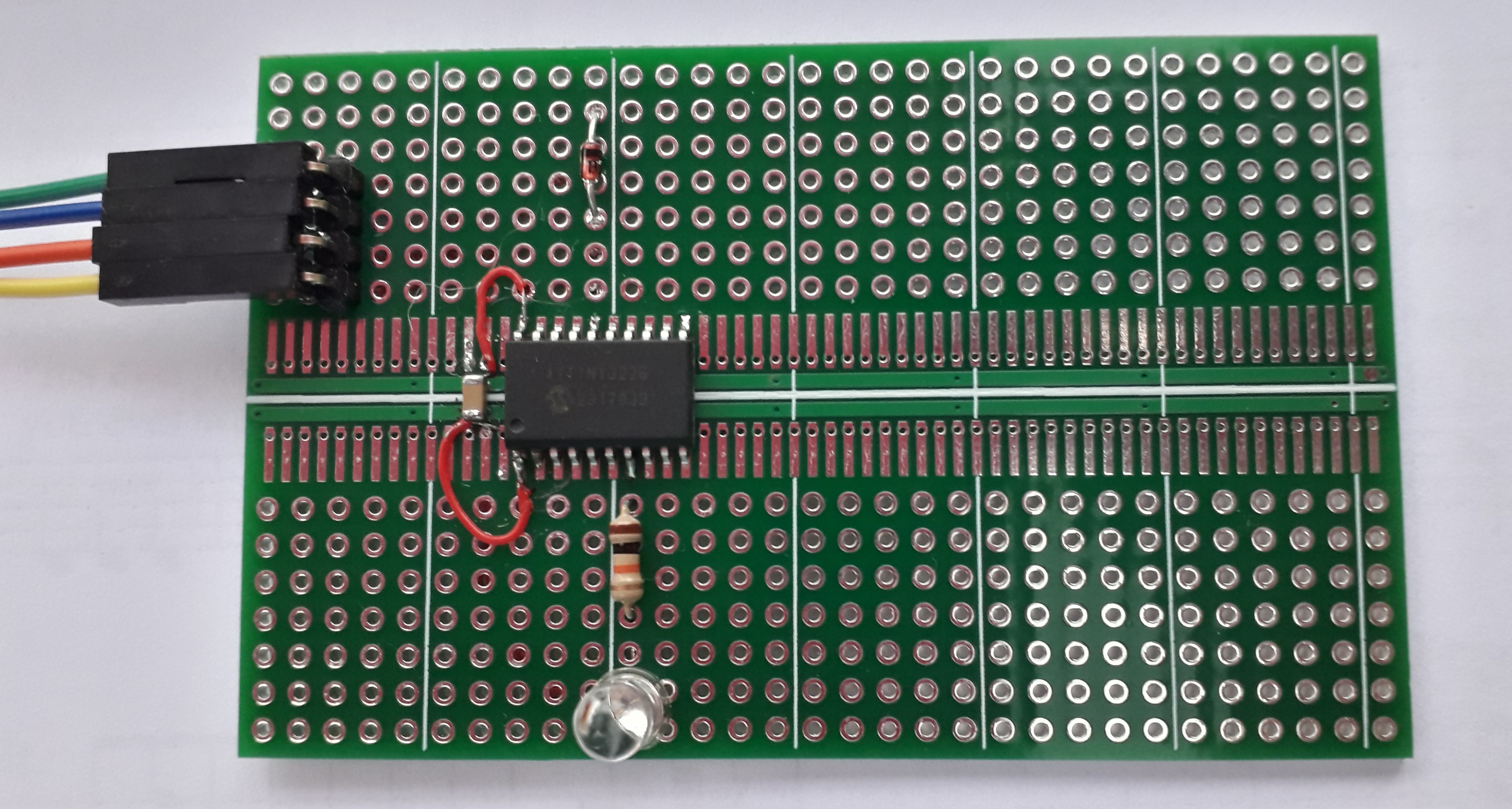
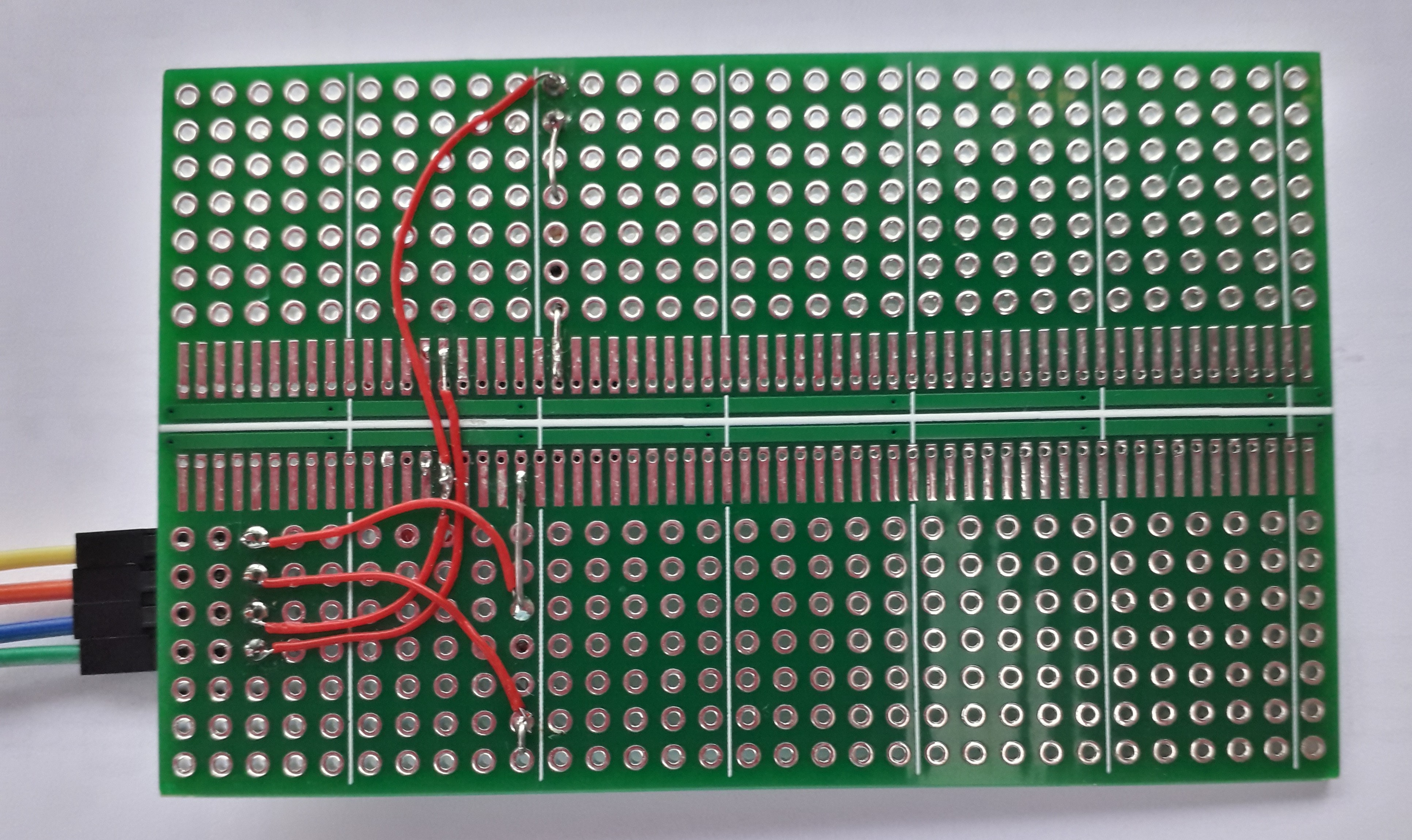
A minimal application with just a single LED can be built as follows:

Once completed, the board may look like:
You can write the software using your favorite editor. A small example to blink the LED in above schematic may look like this: Blink-led example : Main.cpp
Let's go through this source-code step by step:
At the top of the file we have the usual includes. No surprises there.
#include <avr/io.h>
#include <avr/wdt.h>
Then we define a little delay routine, just counting in a loop. Again nothing special. Please note the wdt_reset() inside the loop. This will prevent that the loop is optimised away by the compiler, and it will keep the watchdog happy (if enabled).
void Delay(uint32_t mS)
{  do
   {  wdt_reset();   // To prevent that loop is optimised-away by compiler
   } while(mS--);
}
We are using PB4 to switch the LED. So we better give it a name. I prefer using an enum, especially if there are multiple definitions. Please note the PIN4_bm (Pin 4 bitmap value) that comes from the header file for the Tiny3226.
enum PIN_VALUE
{  // Mapping pin names to bitmap values
   PIN_LED = PIN4_bm,
};
And then we can write the main function:
int main()
{
   CPU_CCP           = CCP_IOREG_gc;  // Unlock Clock control
   CLKCTRL.MCLKCTRLB = 0x00;          // Prescaler off. Run at full speed

   PORTB.DIRSET = PIN_LED;            // Enable PB4 output driver

   for( ;; )
   {  PORTB.OUTSET = PIN_LED;         // Set PB4 high (LED ON)
      Delay( 200000);
      PORTB.OUTCLR = PIN_LED;         // Set PB4 low (LED OFF)
      Delay(1800000);
   }
   return 0;
}
The first 2 lines are needed to get the processor running at max speed. The processor has its prescaler enabled at startup which makes it a bit slow. These 2 instructions will write 0x00 into MCLKCTRLB to switch the prescaler off. But this register is protected against accidental updates, so we need to unlock it first by writing into CPU_CCP.
Next we set our pin to output mode. The tinyAVR-2 chips have nice options to do bit manipulation. A DIRSET register is used to enable the output driver for the LED pin without effecting any other pin in PORTB, as the new value is ORed into PORTB.DIR register.
In the loop, we use the PORTB.OUTSET and PORTB.OUTCLR registers to set and clear the LED pin. Again, only set bits are affected, no worries about any other PINs in the port.
The Delay() function counts down from 1000000 in about half a second so the LED blinks once per second with 2 such delays.
The tinyAVR-2 uses new register names to get the hardware going. Most register names match the names in the processor datasheet, but often there are small differences. And the compiler will not accept such differences. You should look-up these registers in the header file for your processor. The header file for this AtTiny3226 is called "tn3226.h" and should be available in the working directory of your avr-gcc compiler. The compiler selects this file through #include <avr/io.h> and the selected CPU type.
Here we use a simple make file and a command-line avr-gcc compiler because that is the best way to actually see what is happening. The compiler is available at no cost from several locations on the web, for example from Microchip. Just follow the installation instructions. But there is a good chance that the compiler is already available on your system, for example as part of the Arduino installation.
Compiler documentation can be found by the creators of the compiler. See avr-gcc at gnu.org
You can make the compiler accessible from the command-line by adding the compiler location to the PATH environment variable. This can be done as a permanent setting or by using a Setup Script in your project directory. This works both for windows and for Linux systems. To check that you have the correct settings:
avr-gcc --version
On my system (Linux), I have 2 copies of the AVR-gcc compiler. One as a separate download, and one as part of the Arduino installation. A typical compiler installation has the following directory structure:
├── avr
├── bin
├── doc
├── include
├── info
├── lib
├── lib64
├── libexec
├── man
├── share
└── x86_64-pc-linux-gnu
None of the compilers on my system included support for the AtTiny3226. I fixed that by downloading the "Microchip ATtiny Series Device Support" from the Microchip device repository.
We use this makefile for this project. See Make script file : Makefile
In fact, it could just as well be a command-line script. But a Makefile is better at handling macro's and the Makefile syntax is the same on Linux and on Windows. Makefiles have a tendency to become very complicated and unreadable. This makefile example will show that it can be rather simple as well.
This makefile consists of the following sections:
#
# Basic Makefile for a small project.
# Just an example to show all required steps.
#
This optional header just contains comments, as indicated by the hash-signs at the start of each line.
Project = BlinkHere we define a macro with the name of the project. This will be used lateron as filename for several generated output files as in $(Project).elf, $(Project).hex and $(Project).lst, translated into 'Blink.elf', 'Blink.hex' and 'Blink.lst' resp.
DeviceType = attiny3226This macro sets the target device type. This device name must be in lower-case so that it is accepted by avr-gcc as well as by avrdude.
SourceFiles = Main.cppHere we define a macro for a list of source files. At this moment we have only one but you can add additional sourcefiles as your project is growing.
CppOptions  = -mmcu=$(DeviceType)  # Specify target device type
CppOptions += -Wall                # All warnings enabled
CppOptions += -g                   # Include Debug info (Needed for source-code in .lst)
CppOptions += -O2                  # Optimise level 2
Then a macro to set all compiler options. Each option on a separate line so we can add some comments. As you can see, each line adds a new option to the macro using the += (concatenation) operator.
CppOptions += -I ~/AvrGcc/Packages/ATtiny_DFP/1.10.348/include
CppOptions += -B ~/AvrGcc/Packages/ATtiny_DFP/1.10.348/gcc/dev/attiny3226
Here I add some options to the tinyAVR device packages on my machine. These are not needed if the target device is already integrated in the compiler package.
# Do all steps
All : Objects/$(Project).elf Objects/$(Project).hex Objects/Eeprom.hex Objects/$(Project).lst Update
This target "All" is the default target for the make utility as it is the first target in the Makefile. No instructions are added so all inputs are generated unconditionally.
# Generate .elf file from sources
Objects/$(Project).elf : $(SourceFiles)
	mkdir -p Objects
	avr-gcc $(CppOptions) $(SourceFiles)  -o Objects/$(Project).elf
Here we define the elf file as target. We place the elf file (and all other generated files) in its own subdirectory (Objects). As you can see, we use the above defined macros to get the list of sourcefiles and the compiler options. Each command-line must start with a <TAB> character in order to be recognised as a command.
The .elf file is generated by the compiler after compiling each source-file into a .obj file and then linking all .obj files into a firmware package. The .elf file (Executable and Linkable Format) contains the firmware and lots more info that is needed to update the firmware.
# Extract firmware .hex file from .elf
Objects/$(Project).hex  : Objects/$(Project).elf
	avr-objcopy -O ihex -R .eeprom   Objects/$(Project).elf   Objects/$(Project).hex
Here we use avr-objcopy to extract a .hex file from the .elf file. This .hex file contains the actual code that can be downloaded into the target device. Note that the "-R .eeprom" is needed to prevent that the .eeprom section is included in the .hex file
# Extract Eeprom.hex file with eeprom data.
EepromOptions  = -j .eeprom
EepromOptions += --set-section-flags=.eeprom=alloc,load
EepromOptions += --no-change-warnings
EepromOptions += --change-section-lma .eeprom=0
Objects/Eeprom.hex : Objects/$(Project).elf
	avr-objcopy -O ihex $(EepromOptions) Objects/$(Project).elf Objects/Eeprom.hex
Here we use avr-objcopy to generate a separate .hex file for the eeprom data section. This is only needed if your application has default data to initialise data in an eeprom section. This eeprom data can be loaded into the target device eeprom memory if needed.
# Extract listing for examining generated code
Objects/$(Project).lst : Objects/$(Project).elf
	avr-objdump -h --demangle -x  -S Objects/$(Project).elf > Objects/$(Project).lst
Here we use avr-objdump to extract a .lst file from the .elf. This .lst is a text file containing useful information in case you want to see which assembler instructions are generated by the compiler. This works best if you add the -g option to the compiler flags as this includes sourcode statements in the generated .lst file.
The --demangle option will translate the mangled symbol names from the object files back into the original symbol names as in the source files. This is useful for C++ sourcefiles because the compiler 'mangles' symbol names in C++ sources, necessary as the same symbol name can be used for multiple functions (polymorpism and C++ function overloading).
Size :
	avr-size Objects/$(Project).elf
Use avr-size to extract memory usage from the .elf file.
# Write firmware into target processor
UpdiPort = /dev/ttyUSB0
UpdiBaud = 115200
Here we have a macro for the SerialPort that is used for UPDI. This example works on my Debian-Linux machine. On windows I would expect something like '//./COM12' as Updi portname.
AvrDude  = avrdude              # avrdude command
AvrDude += -vv                  # Verbose. Print progress and info. More v's is more data
AvrDude += -c serialupdi        # Use 'serialupdi' as programmer type
AvrDude += -p $(DeviceType)     # Specify target device type
AvrDude += -P $(UpdiPort)       # Comport for UPDI to target
AvrDude += -B $(UpdiBaud)       # Baudrate for UPDI.
This macro specifies the avrdude command along with all required fixed options
Update :
	$(AvrDude) -U flash:w:Objects/$(Project).hex:i
This is the command to use avrdude to download the firmware into the target device. It starts with a macro to call avrdude with most of the -fixed- parameters. And then the Update instruction (with options) to write the .hex file to flash of the target device.
ReadFuses :
	$(AvrDude) -U fuses:r:Fuses.hex:i
Here we use the AvrDude macro again, with a request to read fuse bits from the target device. This generates a "Fuses.hex" with the fuse bytes.
# Delete all generated code
Clean :
	rm -rf Objects/*
And finally a 'Clean' command. To remove all files from the 'Objects' subdirectory.
The make utility is started from the commandline by entering 'make'. This will execute the instructions for the first target in the makefile (All), and all targets that are needed by this target. You can specify the name of the make file using the -f option. The default is 'Makefile' and then it is not needed to specify it (unless it is at some other directory).
make [-f Makefile ]
It is aso possible to specify a target on the commandline. The make utility will then only execute the code for that specific target (and its pre-requisites).
make [-f Makefile ] UpdateIs used to just download the firmware, without compilation (if a hex file is present).
make [-f Makefile ] CleanWill erase everything in the Objects directory.
make [-f Makefile ] ReadFusesWill read the fuse bits from the target controller.
The make-file above uses avrdude to write firmware into the target device. Here I will show what hardware is required to make that work.
Make sure that the serial port signal levels match with the power supply of the target device. A 'High' signal must be above 2/3 VCC so a 3.3V signal level is not reliable on a processor at 5V.
The USB-Serial-port must be connected to the UPDI connector as follows:

The avrdude utility has built-in support for such a setup when "-c serialupdi" is selected as programmer. See Makefile in the previous chapter for the proper command-line.
Make sure to specify the correct UpdiPort in the Makefile.
Fuse bits are used as option switches for the AtTiny3226. The fuse bits can be updated and will have effect on the working of the chip.
The chip comes with factory-set default values and can be used without changing the fuse bits.
The make file contains a script to read the fuse bits into a Fuses.hex file:
make ReadFuses
This results in a Fuses.hex file with the following contents (on a new chip):
:0900000000007EFFFFF6FF000086
:00000001FF
So the default fuses are 00 00 7E FF FF F6 FF 00 00.
So there are 9 fuse bytes. And the function of these bytes is explained in the processors datasheet.
Avrdude can read and write the whole set of fuses in a single command, but it may be more convenient to update individual bytes. for that we examine the output of avrdude -vv where it prints a list of supported memory sections:
                                  Block Poll               Page                       Polled
  Memory Type Alias    Mode Delay Size  Indx Paged  Size   Size #Pages MinW  MaxW   ReadBack
  ----------- -------- ---- ----- ----- ---- ------ ------ ---- ------ ----- ----- ---------
  fuse0       wdtcfg      0     0     0    0 no          1    1      0     0     0 0x00 0x00
  fuse1       bodcfg      0     0     0    0 no          1    1      0     0     0 0x00 0x00
  fuse2       osccfg      0     0     0    0 no          1    1      0     0     0 0x00 0x00
  fuse4       tcd0cfg     0     0     0    0 no          1    1      0     0     0 0x00 0x00
  fuse5       syscfg0     0     0     0    0 no          1    1      0     0     0 0x00 0x00
  fuse6       syscfg1     0     0     0    0 no          1    1      0     0     0 0x00 0x00
  fuse7       append      0     0     0    0 no          1    1      0     0     0 0x00 0x00
  fuse8       bootend     0     0     0    0 no          1    1      0     0     0 0x00 0x00
  fuses                   0     0     0    0 no          9   10      0     0     0 0x00 0x00
  lock                    0     0     0    0 no          1    1      0     0     0 0x00 0x00
  tempsense               0     0     0    0 no          2    1      0     0     0 0x00 0x00
  signature               0     0     0    0 no          3    1      0     0     0 0x00 0x00
  prodsig                 0     0     0    0 no         61   61      0     0     0 0x00 0x00
  sernum                  0     0     0    0 no         10    1      0     0     0 0x00 0x00
  osccal16                0     0     0    0 no          2    1      0     0     0 0x00 0x00
  osccal20                0     0     0    0 no          2    1      0     0     0 0x00 0x00
  osc16err                0     0     0    0 no          2    1      0     0     0 0x00 0x00
  osc20err                0     0     0    0 no          2    1      0     0     0 0x00 0x00
  data                    0     0     0    0 no          0    1      0     0     0 0x00 0x00
  userrow     usersig     0     0     0    0 no         32   32      0     0     0 0x00 0x00
  eeprom                  0     0     0    0 no        256   64      0     0     0 0x00 0x00
  flash                   0     0     0    0 no      32768  128      0     0     0 0x00 0x00
It is not recommended to write all fuses at once, nor to write fuse bytes from a hex file. I would prefer to edit the commands in the makefile and to write known values into the fuse bits. Avrdude supports a special function for this. So the best approach is to define a macro with one or more update commands and all avrdude with that macro.
An update-fuse looks like this for avrdude:
-U fuse0:w:0x00:m
The makefile contains a section to write the factory-default values into the chip. You may want to update the values in this section if you need any changes for your project.
Writing these values into the chip is done from the command-line with:
make WriteFuses
First the good news: PROGMEM is no longer required for tinyAVR-2 processors such as this AtTiny3226. Const data literals are no longer mapped to the precious SRAM data area and reside in flash only. This is a major improvement over legacy AVR processors.
Please note: It is still possible to use PROGMEM and PSTR(), as you did with legacy AVR processors. That will still work on the AtTiny3226. It is just no longer required, and the effects are also slightly different.
The bad news is that you still need PROGMEM and PSTR for all functions that use pgm_read.. library functions. Removing PROGMEM, PSTR, and pgm_read..() will result in programs that work just fine on tinyAVR-2 processors, and will fail on legacy AVRs. So you may choose to continue with PROGMEM, PSTR, and pgm_read() in libraries that should work on both processor families.
The AVR architecture has 2 distinct address area's, one for program space and one for address space. The AVR architectory remains largely the same, but new is the mapping of flash memory into the upper region of the data space. Older AVR processors do not support this mapping so the compiler must treat progmem data very differently.

Both address area's are kept separate within the processor hardware. Each address space has a range of 0x0000 to 0xFFFF, buth they contains different data. The firmware resides in program space, and data resides in data space. It is possible to read data from program space, but only through special instructions (LPM, as used in the <avr/pgmspace.h> library). Normal data access uses data space only (LD, ST etc).
Most programs use pointers. And a pointer is in essence just a 16-bit variable, with a value in the range 0x0000 .. 0xFFFF. You can use the pointer to read from data space, and you can use the same pointer to read from program space, and that will return very different data. For example a pointer value 0x0000 in program space accesses the reset vector of the firmware, while 0x0000 in data space gives the CPU register R0.
The pointer itself does now know the difference between program space and data space. The difference depends solely on how you use the pointer. In normal cases, the pointer is handled as a pointer into data space. If you want to access program space, then you must use dedicated library functions as defined in <avr/pgmspace.h>.
What about pointer types? In your program you can define progmem pointers and data pointers. For example a "char *pText" is a pointer to a character in data space, while a "PGM_P pText" is a pointer to a char in program space. But be aware, this pointer type is only known by the compiler at compile time, and not by the processor. The compiler may use this info to automatically insert pgm_read...() functions.
char Welcome[] = "Hello world";
Here we have an array of 12 chars and this array is placed in data space by the compiler. This is necessary because the application may change the text during running of the firmware. The string literal "Hello world" resides in program space, and is copied into the char array in dataspace during startup of the application.
So this example takes 12 bytes in data space (SRAM) and 12 bytes in program space. No surprises here. The same for legacy AVR and new tinyAVR-2.
const char Welcome[] = "Hello world";
The compiler will generate the correct address for the string in the upper section of data space so that the application can use the data directly, without using pgm_read...() functions.
const char *Welcome = "Hello world";
const char *Welcome = PSTR("Hello world");
This example results in a pointer in data space (SRAM), and a string literal in program space.