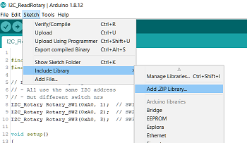
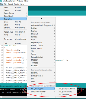
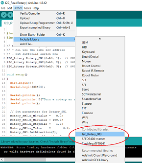
The rotary module can be connected to your arduino using a 4-wire cable. All you need is power and the I2C bus.
| Board | SCL | SDA |
|---|---|---|
| Arduino UNO R3 | A5 | A4 |
| Arduino Nano | A5 | A4 |
| Arduino Pro Mini | A5 | A4 |
| Arduino Mega 2560 | 21 | 20 |
| Arduino Leonardo | 3 | 2 |
Reading the status of the rotary encoders will require a set of interface functions. There are many ways to write an interface module. This library will implement such functions.
For a detailed interface specification: See RotaryEncoder Specification


You need "I2C_Rotary_003/src/I2C_Rotary_003.h".
class I2C_Rotary
Defines a class I2C_Rotary. Can be used to declare rotary objects. Each class object will contain the administration of a single rotary encoder, so you typically need 3 objects. One or each rotary encoder.
I2C_Rotary(byte I2C_Address, byte SwitchId)
Constructor function for I2C_Rotary objects.
byte Button();
Member function. Sends a message to the rotary module to check if the button was pressed.
int Clicks();
Member function. Sends a message to the rotary module to check if the shaft was turned. Returns number of clicks. Negative if turned backwards.
void SetDirection(byte NewDirection)
void SetAccelleration(byte Accelleration)
byte ChangeAddress(byte OldAddress, byte NewAddress)
All member variables can be updated by the application. Just set a new value.
byte m_Address; // I2C address of rotary controller
I2C address. The library uses an 8-bit address. Lowest bit is ignored.
The Arduino Wire library uses a 7-bit address. So this Address is shifted by one position when used.
byte m_Id; // Switch Nr 1 .. 3Contains a Switch number. Range 1 .. 3.
   float m_MaxValue;
   float m_MinValue;   // Limits
User application can set the minimum and maximum value.
User application can set the value of a single click.
Contains the Wire status from the most recent message. Can be used for diagnostics purposes.
Number of bytes of the most recent response message.
Here is an example .ino application that uses the above library. This application prints
the rotary status to the serial port, so you can see what happens when you turn the knobs.
Set limits and configuration for each rotary encoder.
Note that this example sets different direction and Stepsize for the 3 encoders, just to show the possibilities.
You should adjust these values to your needs.
Read the status of each rotary button and save the value is a local variable.
Read the rotation clicks of each rotary and save the value is a local variable.
Print a message when a button is pressed
Print the clicks of each rotary encoder.
You can change the I2C address of the rotary module. The module will then no longer respond to its default address.
In that case you can use this scanner application to check if you have any modules connected on the bus.
This application will try to communicate with all possible addresses on the bus and will try to
interprete the response. Our I2C-Rotary module will respond if its address matches, and will return its name and version
on request.
Tries all even addresses from 0x08 to 0xFE to see if there is a response.
If a response is found, and it is a rotary module, then it reads module and version info
and write a message on the serial port.
Implementation of a function that changes the address of a module on the bus.
The module with the OldAddress is updated to NewAddress.
Here we change address 0xA0 (default) to 0xA2.
The user should connect a single module with default address 0xA0, an that module's address is updated to 0xA2.
Once updated, it will no longer respond to an update request because its address does not match OldAddress anymore.
Prints a message on the serial port to indicate success or failure.
float m_StepSize;
Each click is multiplied by m_Stepsize, so you can select microsteps by setting a small stepsize (like 0.001)
or giant steps by setting a large stepsize (like 1000.0) or anything inbetween.
You can also modify stepsize on the fly, for example by using a button to select between coarse/fine updates.
byte m_XmitStatus; // Communicatio0n status
Value
byte m_RecvCount; //
Examples
Reading Rotary Status
See Example :
You need "I2C_Rotary_003/examples/I2C_ReadRotary"
#include <I2C_Rotary_003.h>
I2C_Rotary Rotary_SW1(0xA0, 1);  // SW1
I2C_Rotary Rotary_SW2(0xA0, 2);  // SW2
I2C_Rotary Rotary_SW3(0xA0, 3);  // SW3
Declare 3 rotary objects, one for each rotary encoder on the board:
   // Set parameters for Rotary_SW1
   Rotary_SW1.m_MinValue =   0.0;
   Rotary_SW1.m_MaxValue = 100.0;
   Rotary_SW1.m_StepSize =   1.0;
   Rotary_SW1.m_Value    =   0.0;
   Rotary_SW1.SetDirection(0);
   Rotary_SW1.SetAccelleration(1);

   // Set parameters for Rotary_SW2
   Rotary_SW2.m_MinValue =  40.0;
   Rotary_SW2.m_MaxValue =  50.0;
   Rotary_SW2.m_StepSize =   0.1;
   Rotary_SW2.m_Value    =  40.0;
   Rotary_SW2.SetDirection(1);
   Rotary_SW2.SetAccelleration(0);

   // Set parameters for Rotary_SW3
   Rotary_SW3.m_MinValue =  -40000.0;
   Rotary_SW3.m_MaxValue =  +40000.0;
   Rotary_SW3.m_StepSize =     100.0;
   Rotary_SW3.m_Value    =   10000.0;
   Rotary_SW3.SetDirection(0);
   Rotary_SW3.SetAccelleration(0);
   // Scan status of the rotary buttons:
   byte Button1 = Rotary_SW1.Button();
   byte Button2 = Rotary_SW2.Button();
   byte Button3 = Rotary_SW3.Button();
   // Scan status of the rotary clicks:
   int  Clicks1 = Rotary_SW1.Clicks();
   int  Clicks2 = Rotary_SW2.Clicks();
   int  Clicks3 = Rotary_SW3.Clicks();
   // Just write the result to the serial port
   if(Button1)
   {  Serial.print( F("SW1 : Button = ") );
      Serial.println( Button1 );
   }
   if(Button2)
   {  Serial.print( F("SW2 : Button = ") );
      Serial.println( Button2 );
   }
   if(Button3)
   {  Serial.print( F("SW3 : Button = ") );
      Serial.println( Button3 );
   }
   if(Clicks1)
   {  Serial.print( F("SW1 : Clicks = ") );
      Serial.println( Clicks1 );
      Serial.print( F("SW1 : Value  = ") );
      Serial.println( Rotary_SW1.m_Value );
   }
   if(Clicks2)
   {  Serial.print( F("SW2 : Clicks = ") );
      Serial.println( Clicks2 );
      Serial.print( F("SW2 : Value  = ") );
      Serial.println( Rotary_SW2.m_Value );
   }
   if(Clicks3)
   {  Serial.print( F("SW3 : Clicks = ") );
      Serial.println( Clicks3 );
      Serial.print( F("SW3 : Value  = ") );
      Serial.println( Rotary_SW3.m_Value );
   }
Scanning Bus
See Example in arduino IDE:
You need "I2C_Rotary_003/examples/I2C_ScanBus"
   // Scan the bus to find all rotary controllers
   byte Count = 0;
   for(uint8_t Address = 8; ; Address += 2)
   {
      if(Address == 0)
      {  // End of the list
         if(Count == 0)
         {  Serial.println( F("Rotary controller not found") );
         }
         break;
      }

      byte Response[20];
      Rotary_SW1.m_Address = Address >> 1;
      Rotary_SW1.ReadRegister( 0xF1, Response, 20 );
      if(Rotary_SW1.m_XmitStatus == 0)
      {  if(    (Rotary_SW1.m_RecvCount > 5)
             && (Response[0] == Address)
             && (Response[1] == 0xF1) )
         {  Serial.print( F("Bingo. Address = 0x") );
            Serial.println(Address, HEX);
            Serial.print( F("Model   = ") );
            Serial.println((const char *) &Response[2]);

            Rotary_SW1.ReadRegister( 0xF2, Response, 20 );
            Serial.print( F("Version = ") );
            Serial.println((const char *) &Response[2]);

            Rotary_SW1.ReadRegister( 0xF3, Response, 20 );
            Serial.print( F("Release = ") );
            Serial.println((const char *) &Response[2]);

            Count += 1;
         }
         else
         {  Serial.print( F("Unknown device at Address = 0x") );
            Serial.println(Address, HEX);
         }
      }
   }
Change I2C Address
See Example in arduino IDE:
You need "I2C_Rotary_003/examples/I2C_ChangeAddress"
void ChangeAddress(byte OldAddress, byte NewAddress)
{
   Serial.println();
   Serial.println();
   Serial.print( F("Change Address from 0x") );
   Serial.print( OldAddress, HEX );
   Serial.print( F(" to 0x") );
   Serial.print( NewAddress, HEX );
   Serial.println();

   switch( Rotary_SW1.ChangeAddress(OldAddress, NewAddress) )
   {  case 0:  Serial.println( F("- New address already set") ); break;
      case 1:  Serial.println( F("- New address occupied")    ); break;
      case 2:  Serial.print  ( F("- Switched to new address 0x") );
               Serial.println( NewAddress, HEX ); break;
      case 3:  Serial.println( F("- Address-change failed")   ); break;
   }
}
void loop()
{
   ChangeAddress(0xA0, 0xA2);
   delay(500);
}